ICGOO在线商城 > 继电器 > 功率继电器,高于 2 A > G2R-2-SN DC24(S)
.jpg)
 Datasheet下载
- 型号: G2R-2-SN DC24(S)
- 制造商: Omron Electronics LLC
- 库位|库存: xxxx|xxxx
- 要求:
| 数量阶梯 | 香港交货 | 国内含税 |
| +xxxx | $xxxx | ¥xxxx |
查看当月历史价格
查看今年历史价格
G2R-2-SN DC24(S)产品简介:
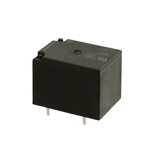
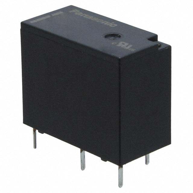
ICGOO电子元器件商城为您提供G2R-2-SN DC24(S)由Omron Electronics LLC设计生产,在icgoo商城现货销售,并且可以通过原厂、代理商等渠道进行代购。 G2R-2-SN DC24(S)价格参考。Omron Electronics LLCG2R-2-SN DC24(S)封装/规格:功率继电器,高于 2 A, 通用 继电器 DPDT(2 Form C) 24VDC 线圈 可插。您可以下载G2R-2-SN DC24(S)参考资料、Datasheet数据手册功能说明书,资料中有G2R-2-SN DC24(S) 详细功能的应用电路图电压和使用方法及教程。
Omron Automation and Safety的G2R-2-SN DC24(S)功率继电器是一款广泛应用于工业自动化和控制系统的元件,其额定电流为5 A(DC),适用于需要较高电流承载能力的场景。以下是该型号继电器的一些典型应用场景:

1. 工业自动化设备:
   - 用于控制各种电动机、电磁阀和传感器的电源通断。例如,在包装机械、输送带系统和自动化生产线中,该继电器可以确保这些设备在需要时可靠地启动或停止。

2. 楼宇自动化系统:
   - 在智能建筑中,G2R-2-SN DC24(S)可用于控制照明系统、空调系统和安防设备。它能够承受较大的电流负载,确保这些系统的稳定运行。

3. 电力控制系统:
   - 用于配电柜、不间断电源(UPS)和其他电力分配设备中,以实现对不同电路的精确控制。特别是在数据中心和通信基站等关键设施中,该继电器能提供可靠的电气隔离和保护。

4. 电动汽车充电站:
   - 在电动汽车充电基础设施中,这款继电器可用于管理充电过程中的大电流路径,确保安全可靠的充电操作。

5. 机器人技术:
   - 在工业机器人和协作机器人中,G2R-2-SN DC24(S)可用于控制伺服电机和其他执行机构的电源供应,支持机器人完成复杂的运动任务。

6. 医疗设备:
   - 某些高精度医疗设备如X光机、超声波诊断仪等也需要使用此类继电器来控制内部组件的电源,确保设备的安全性和准确性。

7. 环境监测与控制:
   - 用于温室、农业灌溉系统以及气象站等环境中,通过控制水泵、风扇等设备的工作状态,维持适宜的生长条件或监测数据采集。

总之,Omron G2R-2-SN DC24(S)功率继电器凭借其稳定的性能和较高的电流承载能力,在众多领域中发挥着重要作用,是构建高效、可靠自动化系统的重要组成部分。
| 参数 | 数值 |
| 产品目录 | |
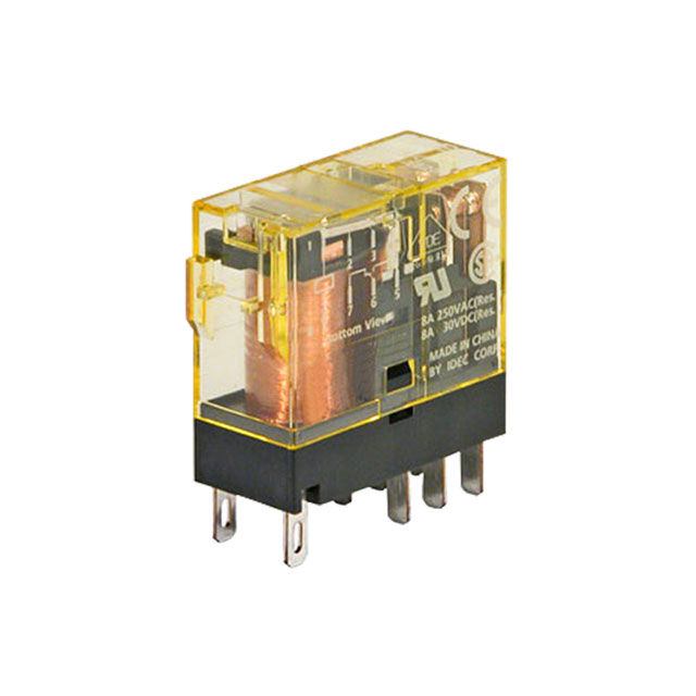
| 描述 | RELAY GEN PURPOSE DPDT 5A 24V |
| 产品分类 | |
| 品牌 | Omron Automation and Safety |
| 数据手册 | |
| 产品图片 |
|
| 产品型号 | G2R-2-SN DC24(S) |
| rohs | 无铅 / 符合限制有害物质指令(RoHS)规范要求 |
| 产品系列 | G2RS |
| 产品目录绘图 |
|
| 产品目录页面 | |
| 关闭电压(最小值) | 3.6 VDC |
| 其它名称 | G2R-2-SN-DC24(S) |
| 包装 | 散装 |
| 安装类型 | 可插 |
| 导通电压(最大值) | 16.8 VDC |
| 工作时间 | 15ms |
| 工作温度 | -40°C ~ 70°C |
| 开关电压 | 380VAC,125VDC - 最小值 |
| 标准包装 | 100 |
| 特性 | LED 指示灯 |
| 相关产品 | /product-detail/zh/P2R-087P/Z3369-ND/1828737/product-detail/zh/P2RF-08-S/Z2059-ND/503125/product-detail/zh/P2RF-08/Z2286-ND/369794/product-detail/zh/P2R-08P/Z2605-ND/369792/product-detail/zh/P2R-08A/Z2284-ND/369791/product-detail/zh/P2RF-08-E/Z207-ND/307723 |
| 端子类型 | 插入式 |
| 线圈功率 | 530 mW |
| 线圈电压 | 24VDC |
| 线圈电流 | 21.6mA |
| 线圈电阻 | 1.1 千欧 |
| 线圈类型 | 无锁存 |
| 继电器类型 | 通用 |
| 触头外形 | DPDT(2 C 型) |
| 触头材料 | - |
| 释放时间 | 10ms |
| 额定接触(电流) | 5A |


.jpg)


- 商务部:美国ITC正式对集成电路等产品启动337调查
- 曝三星4nm工艺存在良率问题 高通将骁龙8 Gen1或转产台积电
- 太阳诱电将投资9.5亿元在常州建新厂生产MLCC 预计2023年完工
- 英特尔发布欧洲新工厂建设计划 深化IDM 2.0 战略
- 台积电先进制程称霸业界 有大客户加持明年业绩稳了
- 达到5530亿美元!SIA预计今年全球半导体销售额将创下新高
- 英特尔拟将自动驾驶子公司Mobileye上市 估值或超500亿美元
- 三星加码芯片和SET,合并消费电子和移动部门,撤换高东真等 CEO
- 三星电子宣布重大人事变动 还合并消费电子和移动部门
- 海关总署:前11个月进口集成电路产品价值2.52万亿元 增长14.8%

PDF Datasheet 数据手册内容提取
General-Purpose Relay G2R- -S (S) @ J140I-E-02 Slim and Space-saving Power Plug-in Relay ■Reduces wiring work by 60% when combined with the LR P2RF-@-PU Push-In Plus Socket (according to actual OMRON measurements). ■Lockable test button models available. ■Built-in mechanical operation indicator. ■Provided with nameplate. ■AC type is equipped with a coil-disconnection self-diagnostic function (LED type). ■High switching power (1-pole: 10 A). For the most recent information on models that have been certified for safety standards, refer to your OMRON website. Model Number Structure Model Number Legend G2R - -S (S) 1 2 3 4 5 1. Number of Poles 4. Rated Coil Voltage 1: 1 pole 5. Mechanical operation indicator and Nameplate 2: 2 poles (S): Models with mechanical operation indicator and Nameplate 2. Terminals S: Plug-in 3. Classification Blank: General-purpose N: LED indicator D: Diode ND: LED indicator and diode NI: LED indicator with test button NDI: LED indicator and diode with test button Note:Contact your OMRON representative for Relays with gold-plated contacts. Ordering Information When your order, specify the rated voltage. List of Models Classification Contact form Coil ratings SPDT DPDT General-purpose G2R-1-S (S) G2R-2-S (S) AC 24, 110, 120, 230, 240 LED indicator G2R-1-SN (S) G2R-2-SN (S) DC 6, 12, 24, 48 LED indicator with test button G2R-1-SNI (S) G2R-2-SNI (S) Diode G2R-1-SD (S) G2R-2-SD (S) LED indicator and diode DC 6, 12, 24, 48 G2R-1-SND (S) G2R-2-SND (S) LED indicator and diode with test button G2R-1-SNDI (S) G2R-2-SNDI (S) Note:1. The standard models are compliant with UL/CSA and VDE standards. Also, an EC compliance declaration has been made for combina- tions with the P2RF-@-E, P2RF-@-S and P2RF-@-PU. The Relays bear the CE Marking. 2. Refer to Connecting Sockets, below, for applicable Socket models. 3. When ordering, add the rated coil voltage and "(S)" to the model number. Rated coil voltages are given in the coil ratings table. Example: G2R-1-S 12 VDC (S) Rated coil voltage 1
G2R-@-S (S) Accessories (Order Separately) Connecting Sockets Track/surface-mounting Socket Back-mounting Socket Push-In Plus Applicable Relay model Screw terminals * PCB terminals Solder terminals Terminal Blocks No. of poles Model Models Models Model P2RF-05 P2R-05P 1 pole G2R-1-S (S) P2RF-05-PU P2R-05A P2RF-05-E P2R-057P P2RF-08 P2R-08P 2 poles G2R-2-S (S) P2RF-08-PU P2R-08A P2RF-08-E P2R-087P *The structure of P2RF-@-E models provides finger protection. Round terminals cannot be used. Use forked crimp terminals. Accessories for Push-In Plus Terminal Block Sockets (P2RF-@-PU) Short Bars Pitch No. of poles Colors Model * Minimum order (quantity) 2 PYDN-7.75-020@ 3 PYDN-7.75-030@ 7.75 mm Red (R) 4 Blue (S) PYDN-7.75-040@ 10 Yellow (Y) 20 PYDN-7.75-200@ 15.5 mm 8 PYDN-15.5-080@ Note:Use the Short Bars for crossover wiring within one Socket or between Sockets. * Replace the box (@) in the model number with the code for the covering color. Labels Minimum order (sheet) Model (quantity per sheet) 5 XW5Z-P4.0LB1 1 sheet (60 pieces) Mounting Tracks Minimum order Applicable Socket Description Model (quantity) 50 cm (l) × 7.3 mm (t): PFP-50N Mounting track 1 m (l) × 7.3 mm (t): PFP-100N --- Track-connecting Socket 1 m (l) × 16 mm (t): PFP-100N2 End plate *1 PFP-M 10 Spacer PFP-S Back-connecting Socket Mounting plate *2 P2R-P 1 *1.When mounting DIN rail, please use End Plate (PFP-M). *2.Used to mount several P2R-05A and P2R-08A Connecting Sockets side by side. 2
G2R-@-S (S) Specifications Coil Ratings Must Must Coil inductance (H) Max. Rated voltage Rated current* Coil (ref. value) ovpoeltraagtee vreolletaagsee voltage conPsouwmeprtion resistance Armature Armature (approx.) 50 Hz 60 Hz % of rated voltage OFF ON 24 V 43.5 mA 37.4 mA 253 Ω 0.81 1.55 110 V 9.5 mA 8.2 mA 5,566 Ω 13.33 26.83 AC 120 V 8.6 mA 7.5 mA 7,286 Ω 16.13 32.46 80% max. 30% max. 110% 0.9VA at 60Hz 230 V 4.4 mA 3.8 mA 27,172 Ω 72.68 143.90 240 V 3.7 mA 3.2 mA 30,360 Ω 90.58 182.34 Must Must Coil inductance (H) Max. Rated voltage Rated current* Coil (ref. value) ovpoeltraagtee vreolletaagsee voltage conPsouwmeprtion resistance Armature Armature (approx.) % of rated voltage OFF ON 6 V 87.0 mA 69 Ω 0.25 0.48 12 V 43.2 mA 278 Ω 0.98 2.35 DC 70% max. 15% min. 110% 0.53W 24 V 21.6 mA 1,113 Ω 3.60 8.25 48 V 11.4 mA 4,220 Ω 15.2 29.82 Note:1. The rated current and coil resistance are measured at a coil temperature of 23°C with tolerances of +15%/-20% for the AC rated current and ±10% for the DC coil resistance. 2. The AC coil resistance and inductance values are reference values only (at 60 Hz). 3. Operating characteristics were measured at a coil temperature of 23°C. 4. The maximum voltage is the maximum possible value of the voltage that can be applied to the relay coil. It is not the maximum voltage that can be applied continuously. Contact Ratings Number of poles 1 pole 2 poles Resistive load Inductive load Resistive load Inductive load Load (cosφ = 1) (cosφ = 0.4; L/R= 7 ms) (cosφ = 1) (cosφ = 0.4; L/R= 7 ms) 10 A at 250VAC; 7.5 A at 250VAC; 5 A at 250VAC; 2 A at 250 VAC; 3 A at Rated load 10 A at 30VDC 5 A at 30 VDC 5 A at 30 VDC 30 VDC Rated carry current 10 A 5 A Max. switching voltage 440 VAC, 125 VDC 380 VAC, 125 VDC Max. switching current 10 A 5 A 2,500VA, 1,875 VA, 1,250 VA, 500 VA, Max. switching power 300 W 150 W 150 W 90 W Failure rate (reference value) * 100 mA at 5 VDC 10 mA at 5 VDC Note:P level: λ60 = 0.1 x 10⁻⁶/operation *This value was measured at a switching frequency of 120 operations per minute. 3
G2R-@-S (S) Characteristics Item 1 pole 2 poles Contact configration SPDT Contact structure Single Contact resistance 100 mΩ max. Operate (set) time 15 ms max. AC: 10 ms max.; DC: 5 ms max. AC: 15 ms max.; DC: 10 ms max. Release (reset) time (w/built-in diode: 20 ms max.) (w/built-in diode: 20 ms max.) Max. operating Mechanical: 18,000 operations/hr frequency Electrical: 1,800 operations/hr (under rated load) Insulation resistance 1,000 MΩ min. (at 500 VDC) 5,000 VAC, 50/60 Hz for 1 min between coil and 5,000 VAC, 50/60 Hz for 1 min between coil and contacts; contacts; Dielectric strength * 3,000 VAC, 50/60 Hz for 1 min between contacts of different polarity 1,000 VAC, 50/60 Hz for 1 min between contacts of 1,000 VAC, 50/60 Hz for 1 min between contacts of same polarity same polarity Destruction: 10 to 55 to 10 Hz, 0.75 mm single amplitude (1.5 mm double amplitude) Vibration resistance Malfunction: 10 to 55 to 10 Hz, 0.75 mm single amplitude (1.5 mm double amplitude) Destruction: 1,000 m/s2 Shock resistance Malfunction: 200 m/s2 when energized; 100 m/s2 when not energized Mechanical: AC coil: 10,000,000 operations min.; Endurance DC coil: 20,000,000 operations min. (at 18,000 operations/hr) Electrical: 100,000 operations min. (at 1,800 operations/hr under rated load) Ambient temperature Operating: –40°C to 70°C (with no icing or condensation) Ambient humidity Operating: 5% to 85% Weight Approx. 20 g Note:Values in the above table are the initial values. *These values are relay only. Prease refer to the “Products Related to Common Sockets and DIN Tracks Data Sheet” for connecting sockets. Approved Standards UL 508 (File No. E41643) IEC/VDE (Certificate No. 40015012 EN 61810-1) Contact Opera- Contact Model Coil ratings Contact ratings Coil ratings Contact ratings Operations form tions form 10 A, 30 VDC (resistive) 6, 12, 24, 48 VDC 5 A, 440 VAC (cosφ = 1.0) G2R-1-S (S) SPDT 10 A, 250 VAC (general use) 100 × 103 1 pole 24, 110, 120, 230, 10 A, 250 VAC (cosφ = 1.0) 100 × 103 240 VAC 10 A, 30 VDC (0 ms) 5 to 110 VDC TV-3 (NO contact only) 25 × 103 6 to 240 VAC 5 A, 30 VDC (resistive) 6, 12, 24, 48 VDC 5 A, 250 VAC (cosφ =1.0) 100 × 103 2 poles 24, 110, 120, 230, 100 × 103 G2R-2-S (S) DPDT 5 A, 250 VAC (general use) 240 VAC 5 A, 30 VDC (0 ms) TV-3 (NO contact only) 25 × 103 LR CSA 22.2 No.0, No.14 (File No. LR31928) Number Coil ratings Contact ratings Operations of poles Contact Opera- 10 A, 250 VAC (general use) Model Coil ratings Contact ratings form tions 5 to 110 VDC 7.5 A, 250 VAC (PF0.4) 1 pole 100 × 103 6 to 240 VDC 10 A, 30 VDC (resistive) 10 A, 30 VDC (resistive) 100 × 103 5A, 30VDC (L/R=7ms) G2R-1-S (S) SPDT 10 A, 250 VAC (general use) 5 A, 250 VAC (general use) 5 to 110 VDC TV-3 (NO contact only) 25 × 103 5 to 110 VDC 2 A, 250 VAC (PF0.4) 6 to 240 VAC 5 A, 30 VDC (resistive) 100 × 103 2 poles 6 to 240 VDC 5 A, 30 VDC (resistive) 100 × 103 G2R-2-S (S) DPDT 5 A, 250 VAC (general use) 3A, 30VDC (L/R=7ms) TV-3 (NO contact only) 25 × 103 4
G2R-@-S (S) Engineering Data Maximum Switching Power G2R-1-S (S) G2R-2-S (S) 100 100 AC inductive load AC resistive A) (cosφ = 0.4) load A) AC inductive load nt ( 10 nt ( 10 (cosφ = 0.4) AloCad resistive e e curr DloCad resistive curr g g DC resistive n n load hi DC inductive load hi witc 1 (L/R = 7 ms) witc 1 D(LC/R i n=d 7u cmtivse) load S S 0.1 1 10 100 1000 0.1 1 10 100 1000 Switching voltage (V) Switching voltage (V) Endurance G2R-1-S (S) G2R-2-S (S) s) 5,000 10,000 on ns)5,000 perati 1,000 2re5s0is-VtiAveC l/o3a0d-VDC eratio 3urance (x10 o 510000 30-VDC induct2(icv5eo0 sl-oφV aA=dC 0( .Li4n/)Rdu =c t7ivme slo)ad 3ance (x10 op 1,051000000 30-VDC in2red5su0isc-VttiiAvveeC l/loo3aa0dd-V (DL/CR = 7ms) d 50 ur 250-VAC n d 50 inductive load E n (cosφ = 0.4) E Switching current (A) Switching current (A) Ambient Temperature vs Maximum Coil Voltage %) e ( g a DC coil olt v m u m AC coil xi a M Ambient temperature (°C) 5
G2R-@-S (S) Dimensions (Unit: mm) Note:All units are in millimeters unless otherwise indicated. SPDT Relays G2R-1-S (S), G2R-1-SN (S), G2R-1-SNI (S) Terminal Arrangement/Internal Connections G2R-1-SD (S), G2R-1-SND (S), G2R-1-SNDI (S) (Bottom View) G2R-1-S (S) G2R-1-SD (S) (DC) 29 max. 13 max. 1 1 5 2 4 3 5 2 4 3 ax. m G2R-1-SN (S), G2R-1-SNI (S) (AC) G2R-1-SN (S), G2R-1-SNI (S) (DC) 5 20 35. 1 1 DC24V 1 5 0.5 4.75 5 2 4 3 5 2 4 3 5 7. G2R-1-SND (S), G2R-1-SNDI (S) (DC) 5.2 5.2 17.5 1 5 2 4 3 DPDT Relays G2R-2-S (S), G2R-2-SN (S), G2R-2-SNI (S) Terminal Arrangement/Internal Connections G2R-2-SD (S), G2R-2-SND (S), G2R-2-SNDI (S) (Bottom View) G2R-2-S (S) G2R-2-SD (S) (DC) 1 2 3 4 29 max. 13 max. 1 2 3 4 8 7 6 5 8 7 6 5 ax. m 5 G2R-2-SN (S), G2R-2-SNI (S) (AC) G2R-2-SN (S), G2R-2-SNI (S) (DC) 20 35. 1 2 3 4 1 2 3 4 0.5 2.5 2.4 6.2 8 7 6 5 8 7 6 5 7.4 8.9 G2R-2-SND (S), G2R-2-SNDI (S) (DC) 5 5 19.4 1 2 3 4 8 7 6 5 6
G2R-@-S (S) Track/Surface Mounting Sockets P2RF-05-PU 56.5 max. Terminal Arrangement/ Internal Connection Diagram (Top View) 52.4 Mounting Hole A2 A1 28.1 (1) (5) Dimensions (3) 27.6 Two M4 screw holes or two 4-dia. holes 108 90 max. Release lever 35.5 12 (2) 14 27.25 (3) 11 (4) (3) 27.6 Note:The numbers in Note:Pull out the hooks to 36.3 mount the Relay 15.5 max. 45 3.9 parentheses are with screws. traditionally used 52.1 terminal numbers. P2RF-08-PU 56.5 max. Terminal Arrangement/ Internal Connection Diagram (Top View) 52.4 Mounting Hole A2 A1 28.1 Dimensions (1) (8) (3) 27.6 Two M4 screw holes or two 4-dia. holes 108 90 max. Release lever 35.5 12 22 (2) (7) 27.25 14 24 (4) (5) 11 21 (3) 27.6 (3) (6) Note:Pull out the hooks to 36.3 mount the Relay 15.5 max. 45 3.9 Note:The numbers in with screws. 52.1 parentheses are traditionally used terminal numbers. Accessories for P2RF-@-PU No. of Maximum Short Bars Application Pitch poles L (Length) Colors Model * carry current PYDN-7.75-@@ (7.75 mm) 2 15.1 PYDN-7.75-020@ 3.90 For Contact 3 22.85 PYDN-7.75-030@ L terminals 7.75 mm Red (R) (common) 4 30.6 Blue (S) PYDN-7.75-040@ 20 A 18.5 20 154.6 Yellow (Y) PYDN-7.75-200@ 12 For Coil 15.5 mm 8 115.85 PYDN-15.5-080@ terminals 2.25 1.57 *Replace the box (@) in the model number with the code for the covering color. Note:1. Use the Short Bars for crossover wiring within one Socket or between Sockets. PYDN-15.5-080@ (15.5 mm) 2. When using short bar to coil terminals of P2RF-@@-PU, A1 terminal cannot be used. In case crossover wiring of A1 terminal side is needed, crossover wiring using A1 3.90 115.85 terminals by wire is possible. Short bar correspondence table 12 18.5 Contact terminal Coil terminal (Common) A1 A2 2.25 1.57 P2RF-@@-PU Available --- ❍ 7
G2R-@-S (S) P2RF-05-E 7±0.2 Terminal Arrangement Mounting Holes (Top View) (for Surface Mounting) 2 Five, M3.5´7 48 max. 3.2-dia. 4 (11) hole 39.5 (12) 2 3 (14) 85.5 max. 35.5 39.5±0.1 3.5-dia. hole M3 or 5 3.5-dia. (A1) 1 hole (A2) 4 11.5 16.0 max. 61 max. Note: Pin numbers in parentheses apply to DIN standard. P2RF-08-E 6+−00..12 Terminal Arrangement Mounting Holes (Top View) (for Surface Mounting) 2 2 1.5 Eight, M3´8 48.0 max. 3 (21) 6 3 (11) 3.2-dia. (22) 7 2 (12) hole 39.5 (24) 5 4 (14) 35.5 85.5 39.5±0.1 max. 3.5-dia. hole 8 (A1) M3 or 3.5-dia. (A2)1 hole 4 11.5 61.0 max. 16.0 max. P2RF-05 7 2 Terminal Arrangement Mounting Holes Five, M3.5 x 8 (Top View) (for Surface Mounting) 4-dia. holes 4.2-dia. hole 71.5 max. 35.5 30±0.05 19.5 4 M3 or 3.2-dia. 19.5 max. 30 max. hole 54 max. P2RF-08 2 7 Eight, M3.5 x 8 Terminal Arrangement Mounting Holes 4-dia. holes (Top View) (for Surface Mounting) 4.2-dia. hole 71.5 max. 35.5 30±0.05 19.5 4 19.5 max. 30 max. M3 or 3.2-dia. 54 max. hole 8
G2R-@-S (S) Mounting Height of Relay with Track/Surface Mounting Sockets P2RF-05-PU G2R-@-S (S) P2RF-08-PU G2R-@-S (S) Relay Relay 63.6 63.6 28.1 28.1 (3.9) (3.9) P2RF-@ G2R-@-S (S) P2RF-@-E GRe2lRay-@-S (S) Relay P2RF-@-E Socket P2RF Socket 66.562.0 67.070.5 Back-connecting Sockets Terminal Arrangement Mounting Holes P2R-05P (1-pole) (Bottom View) 14.5 max. Tolerance: ±0.1 1 4 7 4 Five, 6 1.6-dia. 4.5 6 holes 15 35.5 max. 1.2 4.5 4 15 3.5 1.5 4 (5) 7 4 7 36.5 max. P2R-08P (2-pole) Terminal Arrangement Mounting Holes 4 14.5 max. (Bottom View) 7 0.3 7.5 Eight, 1.3-dia. holes 5 5 35.5 max. 5 20 1 5 2.8 20 1.5 (4.3) 7.5 Terminal plate thickness: 0.3 36.5 max. 9
G2R-@-S (S) P2R-05A (1-pole) 4.5 7.5 14.5 max. 1.2 0.3 Terminal Arrangement 6.7 (Bottom View) 3.8 16.7 5 35.5 max. Panel Cutout Five, 3 x 1.8-dia. holes 13.6±0.1 6 Terminal plate thickness: 0.3 36.5 max. 30.5±0.2 P2R-08A (2-pole) 6.5 7.5 14.5 max. 1.2 0.3 5 5 35.5 max. 20 Recommended thickness of 2.6 the panel is 1.6 to 2.0 mm 2.8 1.5 Eight, 3 x 1.2-dia. holes 7.5 Terminal plate thickness: 0.3 36.5 max. P2R-057P (1-pole) 14 max. 16.4 Terminal Arrangement Mounting Holes 8.7 10.43.5 (Bottom View) 0.7 1 1 4±0.1 Five, 1.6-dia. 6 holes 37 max.29.6 4.515 6±0.1 1 84.75 4.5±0.115±0.1 8.7 7.4 4±0.1 5 7±0.1 41 max. P2R-087P (2-pole) 14 max. 16.4 Terminal Arrangement Mounting Holes 7.5 10.43.5 (Bottom View) 1 0.3 Eight, 7.5 1.3-dia. 5 holes 5 37 max.29.1 1 20 5 5 8.1 20 8.9 7.4 (8.1) 41 max. Mounting Height of Relay with Back-connecting Sockets P2R-@P P2R-@A P2R-@7P G2R-@-S (S) Relay G2R-@-S (S) Relay G2R-@-S (S) Relay 44.5 47.5 PS2oRck-e@tP 38.0 PS2oRck-e@tA P2R-@7P Socket 10
G2R-@-S (S) Mounting Tracks PFP-100N, PFP-50N PFP-100N2 16 7.3±0.15 4.5 4.5 35±0.3 27±0.15 35±0.3 27 24 29.2 15 25 10 25 25 10 25 15 (5) 1 15 2510 25 25 10 25 15 1 1.5 1,000 (500) 1,000 It is recommended to use a panel 1.6 to 2.0 mm thick. End Plate Spacer 16 PFP-M 10 PFP-S 5 12 6.2 1.8 1 50 35.5 35.3 34.8 1.8 44.3 11.5 1.3 10 M4 x 8 pan 4.8 16.5 head screw Mounting Plate P2R-P 90 R2.25 4.5 13.6 10-Ellipse hole 3.4 49 42±0.1 30.5 Square hole 18±0.15 18±0.15 18±0.15 18±0.15 9±0.1 72±0.2 9±0.1 t=1.6 mm Safety Precautions Be sure to read the Common Precautions for All Relay in the website at the following URL: http://www.ia.omron.com/. Refer to Products Related to Common Sockets and DIN Tracks for precautions on the applicable Sockets. Refer to PYF-@@-PU/P2RF-@@-PU for precautions on Push-In Plus Terminal Block Sockets. Warning Indications Indicates a potentially hazardous CAUTION situation which, if not avoided, may result in minor or moderate injury or in property damage. Cation • Do not use the test button for any purpose other than testing. Be sure not to touch the test button accidentally as this will turn the contacts ON. Before using the test button, confirm that circuits, the load, and any other connected item will operate safely. • Check that the test button is released before turning ON relay cir- cuits. • If the test button is pulled out too forcefully, it may bypass the mo- mentary testing position and go straight into the locked position. • Use an insulated tool when you operate the test button. 11
Terms and Conditions of Sale 1. Offer; Acceptance. These terms and conditions (these "Terms") are deemed ITY OR FITNESS FOR A PARTICULAR PURPOSE OF THE PRODUCTS. part of all quotes, agreements, purchase orders, acknowledgments, price lists, BUYER ACKNOWLEDGES THAT IT ALONE HAS DETERMINED THAT THE catalogs, manuals, brochures and other documents, whether electronic or in PRODUCTS WILL SUITABLY MEET THE REQUIREMENTS OF THEIR writing, relating to the sale of products or services (collectively, the "Products") INTENDED USE. Omron further disclaims all warranties and responsibility of by Omron Electronics LLC and its subsidiary companies (“Omron”). Omron any type for claims or expenses based on infringement by the Products or oth- objects to any terms or conditions proposed in Buyer’s purchase order or other erwise of any intellectual property right. (c) Buyer Remedy. Omron’s sole obli- documents which are inconsistent with, or in addition to, these Terms. gation hereunder shall be, at Omron’s election, to (i) replace (in the form 2. Prices; Payment Terms. All prices stated are current, subject to change with- originally shipped with Buyer responsible for labor charges for removal or out notice by Omron. Omron reserves the right to increase or decrease prices replacement thereof) the non-complying Product, (ii) repair the non-complying on any unshipped portions of outstanding orders. Payments for Products are Product, or (iii) repay or credit Buyer an amount equal to the purchase price of due net 30 days unless otherwise stated in the invoice. the non-complying Product; provided that in no event shall Omron be responsi- 3. Discounts. Cash discounts, if any, will apply only on the net amount of invoices ble for warranty, repair, indemnity or any other claims or expenses regarding sent to Buyer after deducting transportation charges, taxes and duties, and will the Products unless Omron’s analysis confirms that the Products were prop- be allowed only if (i) the invoice is paid according to Omron’s payment terms erly handled, stored, installed and maintained and not subject to contamina- and (ii) Buyer has no past due amounts. tion, abuse, misuse or inappropriate modification. Return of any Products by 4. Interest. Omron, at its option, may charge Buyer 1-1/2% interest per month or Buyer must be approved in writing by Omron before shipment. Omron Compa- the maximum legal rate, whichever is less, on any balance not paid within the nies shall not be liable for the suitability or unsuitability or the results from the stated terms. use of Products in combination with any electrical or electronic components, 5. Orders. Omron will accept no order less than $200 net billing. circuits, system assemblies or any other materials or substances or environ- 6. Governmental Approvals. Buyer shall be responsible for, and shall bear all ments. Any advice, recommendations or information given orally or in writing, costs involved in, obtaining any government approvals required for the impor- are not to be construed as an amendment or addition to the above warranty. tation or sale of the Products. See http://www.omron247.com or contact your Omron representative for pub- 7. Taxes. All taxes, duties and other governmental charges (other than general lished information. real property and income taxes), including any interest or penalties thereon, 14.Limitation on Liability; Etc. OMRON COMPANIES SHALL NOT BE LIABLE imposed directly or indirectly on Omron or required to be collected directly or FOR SPECIAL, INDIRECT, INCIDENTAL, OR CONSEQUENTIAL DAMAGES, indirectly by Omron for the manufacture, production, sale, delivery, importa- LOSS OF PROFITS OR PRODUCTION OR COMMERCIAL LOSS IN ANY tion, consumption or use of the Products sold hereunder (including customs WAY CONNECTED WITH THE PRODUCTS, WHETHER SUCH CLAIM IS duties and sales, excise, use, turnover and license taxes) shall be charged to BASED IN CONTRACT, WARRANTY, NEGLIGENCE OR STRICT LIABILITY. and remitted by Buyer to Omron. Further, in no event shall liability of Omron Companies exceed the individual 8. Financial. If the financial position of Buyer at any time becomes unsatisfactory price of the Product on which liability is asserted. to Omron, Omron reserves the right to stop shipments or require satisfactory 15.Indemnities. Buyer shall indemnify and hold harmless Omron Companies and security or payment in advance. If Buyer fails to make payment or otherwise their employees from and against all liabilities, losses, claims, costs and comply with these Terms or any related agreement, Omron may (without liabil- expenses (including attorney's fees and expenses) related to any claim, inves- ity and in addition to other remedies) cancel any unshipped portion of Prod- tigation, litigation or proceeding (whether or not Omron is a party) which arises ucts sold hereunder and stop any Products in transit until Buyer pays all or is alleged to arise from Buyer's acts or omissions under these Terms or in amounts, including amounts payable hereunder, whether or not then due, any way with respect to the Products. Without limiting the foregoing, Buyer (at which are owing to it by Buyer. Buyer shall in any event remain liable for all its own expense) shall indemnify and hold harmless Omron and defend or set- unpaid accounts. tle any action brought against such Companies to the extent based on a claim 9. Cancellation; Etc. Orders are not subject to rescheduling or cancellation that any Product made to Buyer specifications infringed intellectual property unless Buyer indemnifies Omron against all related costs or expenses. rights of another party. 10.Force Majeure. Omron shall not be liable for any delay or failure in delivery 16.Property; Confidentiality. Any intellectual property in the Products is the exclu- resulting from causes beyond its control, including earthquakes, fires, floods, sive property of Omron Companies and Buyer shall not attempt to duplicate it strikes or other labor disputes, shortage of labor or materials, accidents to in any way without the written permission of Omron. Notwithstanding any machinery, acts of sabotage, riots, delay in or lack of transportation or the charges to Buyer for engineering or tooling, all engineering and tooling shall requirements of any government authority. remain the exclusive property of Omron. All information and materials supplied 11.Shipping; Delivery. Unless otherwise expressly agreed in writing by Omron: by Omron to Buyer relating to the Products are confidential and proprietary, a.Shipments shall be by a carrier selected by Omron; Omron will not drop ship and Buyer shall limit distribution thereof to its trusted employees and strictly except in “break down” situations. prevent disclosure to any third party. b.Such carrier shall act as the agent of Buyer and delivery to such carrier shall 17.Export Controls. Buyer shall comply with all applicable laws, regulations and constitute delivery to Buyer; licenses regarding (i) export of products or information; (iii) sale of products to c.All sales and shipments of Products shall be FOB shipping point (unless oth- “forbidden” or other proscribed persons; and (ii) disclosure to non-citizens of erwise stated in writing by Omron), at which point title and risk of loss shall regulated technology or information. pass from Omron to Buyer; provided that Omron shall retain a security inter- 18.Miscellaneous. (a) Waiver. No failure or delay by Omron in exercising any right est in the Products until the full purchase price is paid; and no course of dealing between Buyer and Omron shall operate as a waiver d.Delivery and shipping dates are estimates only; and of rights by Omron. (b) Assignment. Buyer may not assign its rights hereunder e.Omron will package Products as it deems proper for protection against nor- without Omron's written consent. (c) Law. These Terms are governed by the mal handling and extra charges apply to special conditions. law of the jurisdiction of the home office of the Omron company from which 12.Claims. Any claim by Buyer against Omron for shortage or damage to the Buyer is purchasing the Products (without regard to conflict of law princi- Products occurring before delivery to the carrier must be presented in writing ples). (d) Amendment. These Terms constitute the entire agreement between to Omron within 30 days of receipt of shipment and include the original trans- Buyer and Omron relating to the Products, and no provision may be changed portation bill signed by the carrier noting that the carrier received the Products or waived unless in writing signed by the parties. (e) Severability. If any provi- from Omron in the condition claimed. sion hereof is rendered ineffective or invalid, such provision shall not invalidate 13.Warranties. (a) Exclusive Warranty. Omron’s exclusive warranty is that the any other provision. (f) Setoff. Buyer shall have no right to set off any amounts Products will be free from defects in materials and workmanship for a period of against the amount owing in respect of this invoice. (g) Definitions. As used twelve months from the date of sale by Omron (or such other period expressed herein, “including” means “including without limitation”; and “Omron Compa- in writing by Omron). Omron disclaims all other warranties, express or implied. nies” (or similar words) mean Omron Corporation and any direct or indirect (b) Limitations. OMRON MAKES NO WARRANTY OR REPRESENTATION, subsidiary or affiliate thereof. EXPRESS OR IMPLIED, ABOUT NON-INFRINGEMENT, MERCHANTABIL- Certain Precautions on Specifications and Use 1. Suitability of Use. Omron Companies shall not be responsible for conformity ADDRESS THE RISKS, AND THAT THE OMRON’S PRODUCT IS PROP- with any standards, codes or regulations which apply to the combination of the ERLY RATED AND INSTALLED FOR THE INTENDED USE WITHIN THE Product in the Buyer’s application or use of the Product. At Buyer’s request, OVERALL EQUIPMENT OR SYSTEM. Omron will provide applicable third party certification documents identifying 2. Programmable Products. Omron Companies shall not be responsible for the ratings and limitations of use which apply to the Product. This information by user’s programming of a programmable Product, or any consequence thereof. itself is not sufficient for a complete determination of the suitability of the Prod- 3. Performance Data. Data presented in Omron Company websites, catalogs uct in combination with the end product, machine, system, or other application and other materials is provided as a guide for the user in determining suitabil- or use. Buyer shall be solely responsible for determining appropriateness of ity and does not constitute a warranty. It may represent the result of Omron’s the particular Product with respect to Buyer’s application, product or system. test conditions, and the user must correlate it to actual application require- Buyer shall take application responsibility in all cases but the following is a ments. Actual performance is subject to the Omron’s Warranty and Limitations non-exhaustive list of applications for which particular attention must be given: of Liability. (i) Outdoor use, uses involving potential chemical contamination or electrical 4. Change in Specifications. Product specifications and accessories may be interference, or conditions or uses not described in this document. changed at any time based on improvements and other reasons. It is our prac- (ii) Use in consumer products or any use in significant quantities. tice to change part numbers when published ratings or features are changed, (iii)Energy control systems, combustion systems, railroad systems, aviation or when significant construction changes are made. However, some specifica- systems, medical equipment, amusement machines, vehicles, safety equip- tions of the Product may be changed without any notice. When in doubt, spe- ment, and installations subject to separate industry or government regulations. cial part numbers may be assigned to fix or establish key specifications for (iv)Systems, machines and equipment that could present a risk to life or prop- your application. Please consult with your Omron’s representative at any time erty. Please know and observe all prohibitions of use applicable to this Prod- to confirm actual specifications of purchased Product. uct. 5. Errors and Omissions. Information presented by Omron Companies has been NEVER USE THE PRODUCT FOR AN APPLICATION INVOLVING SERIOUS checked and is believed to be accurate; however, no responsibility is assumed RISK TO LIFE OR PROPERTY OR IN LARGE QUANTITIES WITHOUT for clerical, typographical or proofreading errors or omissions. ENSURING THAT THE SYSTEM AS A WHOLE HAS BEEN DESIGNED TO
OMRON AUTOMATION AMERICAS HEADQUARTERS • Chicago, IL USA • 847.843.7900 • 800.556.6766 • www.omron247.com OMRON CANADA, INC. • HEAD OFFICE OMRON ARGENTINA • SALES OFFICE Toronto, ON, Canada • 416.286.6465 • 866.986.6766 • www.omron247.com Cono Sur • 54.11.4783.5300 OMRON ELECTRONICS DE MEXICO • HEAD OFFICE OMRON CHILE • SALES OFFICE México DF • 52.55.59.01.43.00 • 01-800-226-6766 • mela@omron.com Santiago • 56.9.9917.3920 OMRON ELECTRONICS DE MEXICO • SALES OFFICE OTHER OMRON LATIN AMERICA SALES Apodaca, N.L. • 52.81.11.56.99.20 • 01-800-226-6766 • mela@omron.com 54.11.4783.5300 OMRON ELETRÔNICA DO BRASIL LTDA • HEAD OFFICE São Paulo, SP, Brasil • 55.11.2101.6300 • www.omron.com.br OMRON EUROPE B.V. • Wegalaan 67-69, NL-2132 JD, Hoofddorp, The Netherlands. • +31 (0) 23 568 13 00 • www.industrial.omron.eu Authorized Distributor: Controllers & I/O • Machine Automation Controllers (MAC) • Motion Controllers • Programmable Logic Controllers (PLC) • Temperature Controllers • Remote I/O Robotics • Industrial Robots • Mobile Robots Operator Interfaces • Human Machine Interface (HMI) Motion & Drives • Machine Automation Controllers (MAC) • Motion Controllers • Servo Systems • Frequency Inverters Vision, Measurement & Identification • Vision Sensors & Systems • Measurement Sensors • Auto Identification Systems Sensing • Photoelectric Sensors • Fiber-Optic Sensors • Proximity Sensors • Rotary Encoders • Ultrasonic Sensors Safety • Safety Light Curtains • Safety Laser Scanners • Programmable Safety Systems • Safety Mats and Edges • Safety Door Switches • Emergency Stop Devices • Safety Switches & Operator Controls • Safety Monitoring/Force-guided Relays Control Components • Power Supplies • Timers • Counters • Programmable Relays • Digital Panel Meters • Monitoring Products Switches & Relays • Limit Switches • Pushbutton Switches • Electromechanical Relays • Solid State Relays Software • Programming & Configuration • Runtime J140I-E-02 04/16 N o te: Specifications are subject to change. © 2016 Omron. All Rights Reserved. Printed in U.S.A. Printed on recycled paper.